This is the old site. Please use the new site.

  Welcome, Guest. Please Login
Omega Owners Forum
 
  Home Shop Help Search Members Login  
 

This is the old site. Please use the new site.

www.omegaowners.com/forum/index.php.

 
Page Index Toggle Pages: 1
Send Topic Print
Engine Theory Part 4 - Camshaft Details (Read 2046 times)
Marks DTM Calib
Administrator
****************
Offline


Ex Member

Posts: 25671
Northern Hemisphere
Gender: male

Drives: Astra J, Mum Bus, Dexta Tractor, 108 DMU wip
Engine Theory Part 4 - Camshaft Details
30. Sep 2008 at 10:52
 
The camshaft is a very complex part of the engine and, as we have already discussed, is critical to getting the characteristics of the unit to suit the desired application.

Here we will simply look at the various items of terminology used to describe a camshafts profile.
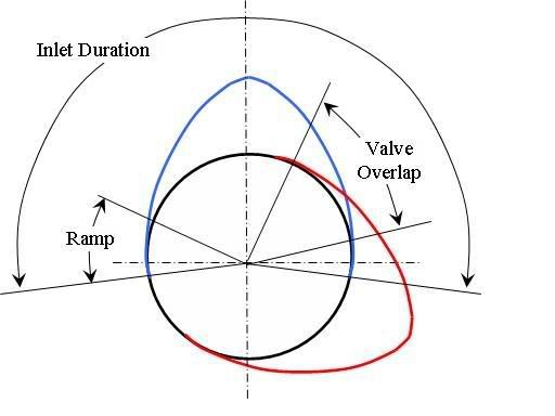
...


The above diagram shows 2 important measures of a camshaft, these being the duration and valve overlap. The valve ramp is also included in this pic

Duration

The duration describes the period which the valve is open for from the moment it lifts off its seat until its sealed against its seat again. This is usualy quoted in CRANK shaft degrees (important to note this as its rarely quoted in camshaft degrees)

Ramp

This is the point where we start to accelerate a valve (open it)

Valve Overlap

Covered in Part 3, this is the point where both valves are open at the same time
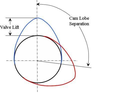
...

Valve Lift

The theory behind this was covered in Part 2 and is described as the difference between the nose (peek lobe height) and base circle of the cam.

Seperation

This is the angle between the nose (peek lobe height) of the inlet and exhaust cam

Other parts of the cam
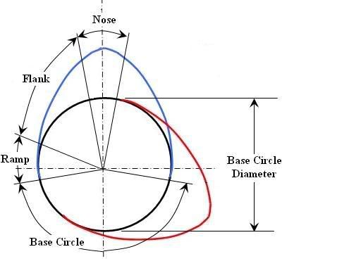
...
Back to top
« Last Edit: 30. Sep 2008 at 10:56 by Marks DTM Calib »  
Marks DTM Calib  
IP Logged
 
Marks DTM Calib
Administrator
****************
Offline


Ex Member

Posts: 25671
Northern Hemisphere
Gender: male

Drives: Astra J, Mum Bus, Dexta Tractor, 108 DMU wip
Re: Engine Theory Part 4 - Camshaft Details
Reply #1 - 30. Sep 2008 at 11:11
 
cem wrote on 30. Sep 2008 at 11:07:
if I'm not wrong
Blue inlet , red exhaust isnt it  Undecided


It depends which way the cam turns but yes, that is the correct assumption in this case.
Back to top
 
Marks DTM Calib  
IP Logged
 
markey mark
BANNED
Offline


banned for repeatedly
reneaging on deals.

Posts: 1
scunthorpe north lincs
Gender: male

Drives: 99 mv6 est leather & 19"s
Re: Engine Theory Part 4 - Camshaft Details
Reply #2 - 30. Sep 2008 at 11:12
 
pm sent mark  Thumbs Up!
Back to top
 
markey mark mark.payne84  
IP Logged
 
cem
Omega King
********
Offline


Posts: 13920
Ankara/Turkey
Gender: male

Drives: 97 2.5 V6 Manual CD- Clio Sport
Re: Engine Theory Part 4 - Camshaft Details
Reply #3 - 30. Sep 2008 at 11:13
 
wrong question message understood Embarrassed
Back to top
 
cem  
IP Logged
 
Bandit127
Omega Knight
*****
Offline


Posts: 1345
Hedge End, Southampton
Gender: male

Drives: MY99 MV6 3.0
Re: Engine Theory Part 4 - Camshaft Details
Reply #4 - 30. Sep 2008 at 23:06
 
Thanks or another great article Mark. I have a question or two..

I haven't quite got my head around the profile of the cam lobe yet. But I presume in general terms that the ramp, flank and nose put together impose a half sine wave on the base circle?

The full sine wave would have a frequency of 'duration' x 2 and the amplitude would be 'lift' x 2?

If it isn't a half sine wave then Mr Fourier would say that the higher harmonics would tend to create valve bounce. Or have I lost the plot?

Thanks,
Jim


Back to top
« Last Edit: 30. Sep 2008 at 23:08 by Bandit127 »  
WWW  
IP Logged
 
Page Index Toggle Pages: 1
Send Topic Print

This is the old site. Please use the new site.